How This Works
Overview
This guide explains how to plan and set up observation stations for measuring impact distances during live trebuchet launches. It covers how baseline distance determines measurement accuracy, how to calculate the optimal baseline for your expected throwing distance, and where the point of diminishing returns lies.
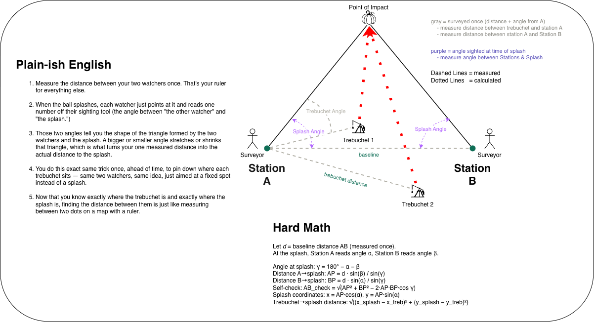
The Short Version: Two Spotters Find One Impact
Imagine two people standing at fixed observation points, both pointing at the same point of impact. Each person's sight line is like an invisible string stretching across the target area. The place where those two strings cross is the point of impact.
We measure the distance between the two observation stations just once. That distance is called the baseline. Together, the baseline and the two sight lines form a triangle. Knowing one side and the two corner angles is enough for the computer to work out the point of impact.
The spotters do not need to do any math:
- At Station A, point the angle gauge toward Station B and call that zero. When the impact happens, turn toward it and report how many degrees you turned.
- At Station B, do the reverse: zero toward Station A, then turn toward the same impact and report that angle.
- The submitter selects the firing trebuchet and enters both readings. The website calculates the distance and adds the result to the live shot log.
The angle is measured at the station, between the direction toward the other station and the direction toward the impact. It is not the trebuchet's firing angle and not an absolute compass bearing.
Why We Survey Each Trebuchet
The triangle tells us how far the impact is from Station A, but the trebuchet may be somewhere else! Before the event, we measure each trebuchet's distance and angle from A. The computer uses that fixed starting position to calculate the straight-line distance from the firing trebuchet to the impact. If no trebuchet is selected, it measures from Station A instead.
What the Visualizers Show
The satellite map uses optional station GPS coordinates to place station, trebuchet, and impact icons over the target area. The schematic shows the same layout on a simple plot without needing GPS. The icons and shot log update as new readings arrive.
GPS is only used to position the map overlay. The layout is scaled to fit both GPS station positions, so it agrees with the schematic even if GPS puts the stations a different distance apart than the measured baseline. The map is an illustration, not a distance measurement: plotted locations and map distances may be inaccurate. The competition distance comes from the measured baseline, trebuchet survey, and two sighting angles entered in the forms, never from GPS. Those inputs remain unchanged by map scaling. A convincing-looking map does not guarantee accurate readings: both spotters must sight the same impact and use the correct zero direction, and calculated accuracy depends on the field measurements.
The Math Behind the Result
You can skip this section during the event; the website performs every step.
1. Finish the Triangle
Let
Both station readings must be greater than zero and their sum must be less than 180 degrees. Otherwise, the website rejects the readings and asks for a correction.
2. Find the Distances from the Stations
The law of sines links each side of a triangle to the angle opposite it. This gives the distance from A to the impact (
The inputs are in degrees; the code converts them to radians before using sine or cosine.
For example, if the baseline is 50 feet and both spotters report 60 degrees, the third angle is also 60 degrees. All three sides are equal, so the impact is 50 feet from each station.
3. Put the Impact and Trebuchet on the Same Plot
Think of Station A as the starting dot on a sheet of graph paper. The direction from A toward B runs to the right. Positive angles point into the target area.
The impact position is:
A trebuchet surveyed at distance
Trebuchets behind the baseline have negative survey angles.
4. Measure from the Trebuchet to the Impact
The Pythagorean theorem combines the horizontal and vertical differences between the two points into one straight-line distance:
With no trebuchet selected, the starting point is Station A and the distance is simply
5. Check the Calculation
The law of cosines reconstructs the baseline from the calculated triangle:
This should match the entered baseline, apart from rounding. It checks the calculation's internal consistency, not the accuracy of the spotters: even inaccurate angles that form a valid triangle will reconstruct the same baseline. Careful sighting, a suitable baseline, and practice shots are what improve real-world accuracy.
For calibration, you can optionally enter a known actual distance. The displayed error percentage is:
Use a positive known distance for this comparison. It is not required for normal event logging.
Is the Baseline the Primary Factor Under Your Control
Yes. Your assumption is spot on: the baseline distance between Station A and Station B is the single most impactful variable you control when setting up the field.
Here is why:
- The trebuchet location is fixed: Once you set up your trebuchet and survey its distance and angle from Station A, that position is simply an offset subtraction. It shifts the reference origin, but does not alter the geometric shape of the sighting triangle.
- The impact location is determined by the throw: You cannot choose where the projectile lands.
- The baseline length (
) dictates the convergence angle ( ): Because the spotters sight the impact from both ends of the baseline, the baseline length determines whether the sightlines form a well-defined triangle or two nearly parallel lines.
While sighting tool quality (such as a calibrated alidade or optical transit vs. a visual sight) also matters, baseline selection determines how severely small sighting mistakes get magnified.
How to Determine Your Baseline from Maximum Distance
The Golden Ratio of Triangulation
A proven rule of thumb for field triangulation is:
Set your baseline to between 25% and 40% (1/4 to 1/3) of your maximum expected throw distance.
| Max Expected Throw | Recommended Baseline | Baseline Ratio | Typical Convergence at Max Throw |
|---|---|---|---|
| 200 ft | 75 to 100 ft | ~1:2 | 28 deg to 36 deg |
| 500 ft | 150 to 200 ft | ~1:3 | 17 deg to 22 deg |
| 1,000 ft | 250 to 350 ft | ~1:3 to 1:4 | 14 deg to 20 deg |
| 2,000 ft | 500 to 650 ft | ~1:3 to 1:4 | 14 deg to 18 deg |
Why This Ratio Works
When a projectile lands at distance
For distant shots (
As long as the apex angle stays above 12 to 15 degrees, small sighting errors produce modest distance errors. When the apex angle drops below 5 to 6 degrees, distance errors explode rapidly.
Accuracy and Error Propagation
In optical triangulation, distance error (
where:
is the distance from the baseline to the impact. is your baseline length. is the angular error of the spotters (in radians).
Key Takeaways from the Error Equation
- Distance error grows with the square of range (
): A 2,000 ft shot has 4 times the sensitivity to error as a 1,000 ft shot, and 16 times that of a 500 ft shot. - Error is inversely proportional to baseline (
): Doubling your baseline cuts your distance error in half for the exact same spotter readings.
Realistic Error Matrix
Assuming a typical field spotter error of
| Target Distance | Baseline = 100 ft | Baseline = 250 ft | Baseline = 500 ft | Baseline = 1,000 ft |
|---|---|---|---|---|
| 100 ft | +/- 1.9 ft (1.7%) | +/- 1.1 ft (0.7%) | +/- 0.9 ft (0.3%) | +/- 0.9 ft (0.2%) |
| 200 ft | +/- 6.9 ft (3.4%) | +/- 3.2 ft (1.4%) | +/- 2.2 ft (0.7%) | +/- 1.9 ft (0.3%) |
| 500 ft | +/- 40.3 ft (8.0%) | +/- 17.4 ft (3.4%) | +/- 9.6 ft (1.7%) | +/- 6.1 ft (0.9%) |
| 1,000 ft | +/- 148.8 ft (14.9%) | +/- 65.7 ft (6.5%) | +/- 34.7 ft (3.4%) | +/- 19.1 ft (1.7%) |
| 2,000 ft | +/- 517.6 ft (25.9%) | +/- 245.5 ft (12.2%) | +/- 131.5 ft (6.5%) | +/- 69.5 ft (3.4%) |
Notice what happens at a 2,000 ft shot:
- With a 100 ft baseline, a
sighting error produces a 517 ft error (completely unusable). - Expanding the baseline to 500 ft reduces that error to 131 ft (6.5%).
The Point of Diminishing Returns
If a longer baseline is always more accurate, why not make it 2,000 or 3,000 feet?
The point of diminishing returns usually happens when the baseline exceeds 40% to 50% of the maximum throw (or roughly 500 to 700 feet in practice). Extending beyond that introduces severe trade-offs:
1. The Short-Shot Blindspot (Obtuse Triangle Problem)
If you establish an enormous baseline (e.g. 1,000 ft) to capture 2,000 ft throws, but a trebuchet misfires or throws a short 100 or 200 ft shot:
- The impact angle approaches
to . - Spotters are looking almost directly toward each other rather than into the target area.
- In this flattened geometry, any tiny error in angle causes massive instability in calculating whether the impact was left, right, in front of, or behind the baseline.
2. Terrain and Line-of-Sight
- Real measurement sites may have uneven terrain, structures, vegetation, and other obstructions.
- Finding 500 feet of unobstructed, straight line-of-sight between Station A and Station B is feasible at many sites.
- Finding 1,500 to 2,000 feet of uninterrupted line-of-sight is often difficult.
3. Spotter Coordination and Impact Identification
- The visible evidence of an impact may disappear quickly.
- Spotters separated by 1,000+ feet need clear radio communication and rapid confirmation that they are sighting the same point of impact.
4. Mathematical Diminishing Returns
Error follows a
- Increasing baseline from 100 ft to 500 ft eliminates 75% of the distance error.
- Increasing baseline from 500 ft to 1,000 ft only eliminates an additional 12% of the original error, while doubling the required physical space and setup complexity.
Field Setup Checklist
Step 1: Establish Your Baseline
- Pick two observation points (Station A on the left, Station B on the right when looking toward the target area).
- Measure the straight-line distance
between Station A and Station B using a surveyor tape, laser rangefinder, or GPS RTK. - Verify that Station A can see Station B, and both stations have clear views across the entire target area.
Step 2: Zero the Sighting Instruments
- Station A: Sight directly at Station B and set the angle gauge to
. Angles sweep counterclockwise (or positive into the target area) toward the impact. - Station B: Sight directly back at Station A and set the angle gauge to
. Measure the positive interior angle toward the impact on the target side (the opposite turning direction to Station A).
Step 3: Survey the Trebuchets
For each trebuchet on site:
- Measure the straight-line distance from Station A to the pivot/release pin of the trebuchet.
- Measure the angle from Station A to the trebuchet relative to the baseline (
along line AB toward Station B, toward the target area). If the trebuchet is set up behind the baseline, enter a negative angle (down to , where points directly away from the target area). - Enter the name, distance, and angle in the Trebuchet Setup section of the tracker.
Step 4: Live Event Logging
- When a projectile launches, spotters at Station A and Station B track the flight and lock their sights on the impact center.
- Both spotters radio in their angle:
angAfrom Station A andangBfrom Station B. - The operator selects the firing trebuchet, enters the two angles, and logs the shot.
- Check the Baseline Self-Check column in the table:
- The check should match the measured baseline
apart from rounding. This is an internal calculation check, not proof of accurate sighting. - If the system rejects either nonpositive angle or angles whose sum is at least 180 degrees, re-enter the readings. If the check differs significantly, investigate the calculation or input data.
- The check should match the measured baseline